Friday, October 27, 2017

DYI: Kawasaki Ninja 650 2017 USB socket for $5

I wanted to install 12V (cigarette lighter) socket into my new Ninja 650 motorbike. I couldn't believe Kawasaki price - almost 130USD (!!!) for the socket itself. Installation fee is counted separately. 

Insane? Definitely. 

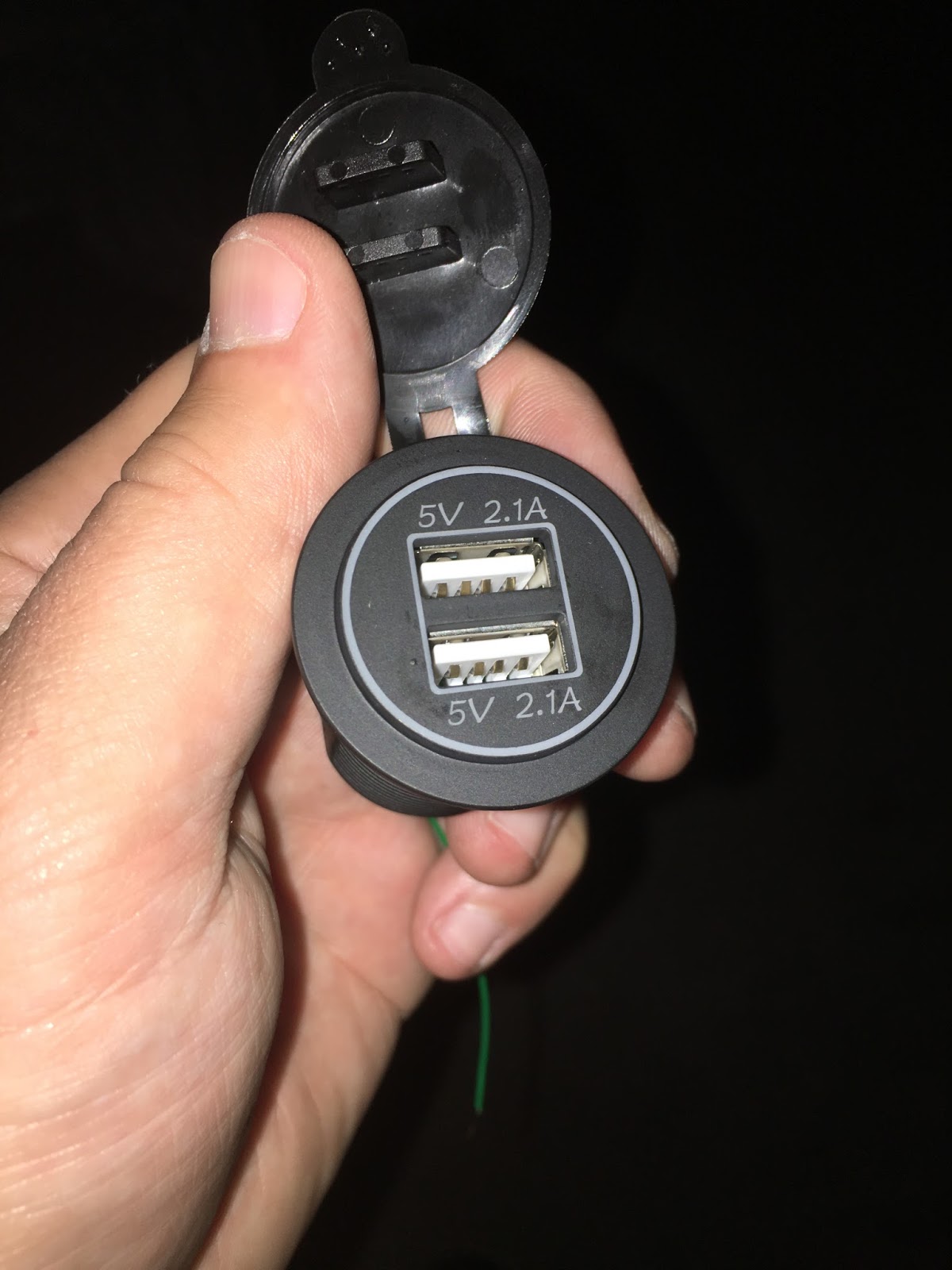
Doing it myself, I have installed "native", double USB socket with a bit of patience and less than $5.


I went to my favourite Chinese portal and bought this one for $4.24 including shipping. By the way, I mentioned patience before, cause it takes a bit to ship from China.


Installation is almost as easy as connecting the cables. They are already prepared and routed, but let's start from the beginning.
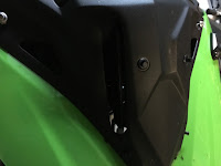
Step 1:
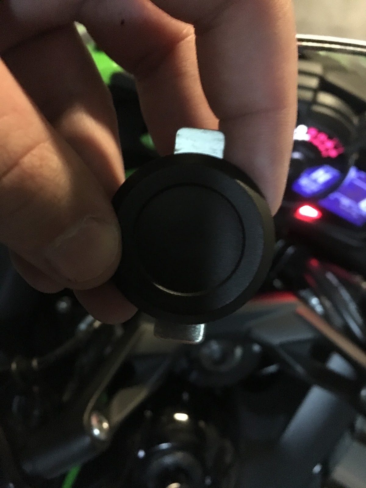
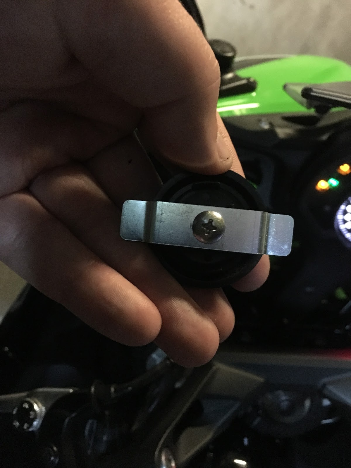
Remove 12V Socket plug from the dashboard. It's secured by one screw from the bottom so it's a bit inconvenient, but with medium screwdriver it can be done without removing any other part of bike:


Step 2:
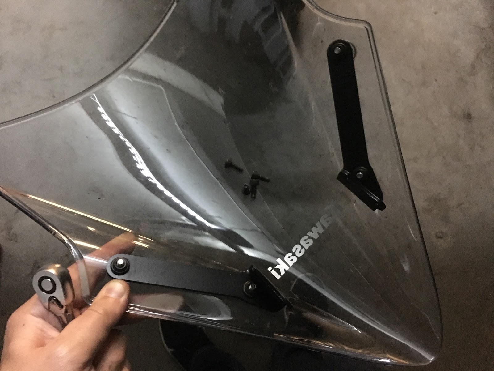
Remove windscreen. In my case it was easier then usual because I already moved it to middle position. I managed to remove it together with mounting rails:


Step 3:
Remove front black panel by pushing center of 4 clips and removing two screws:
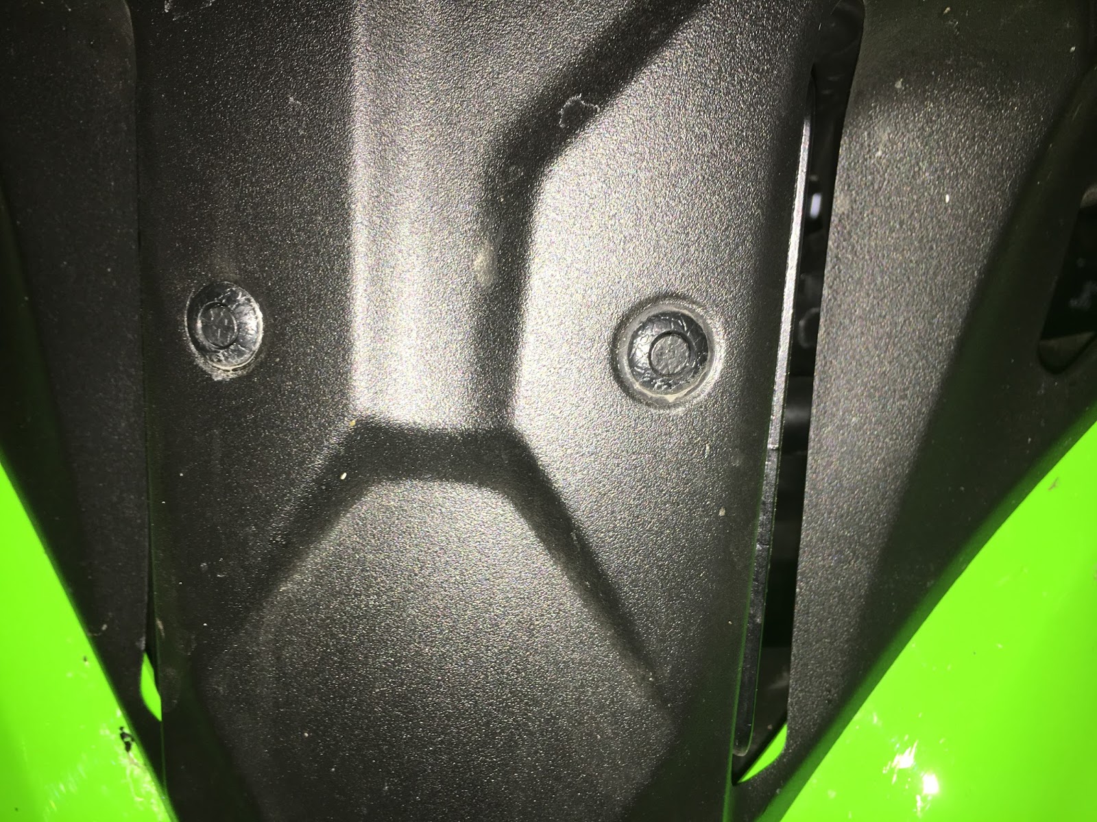
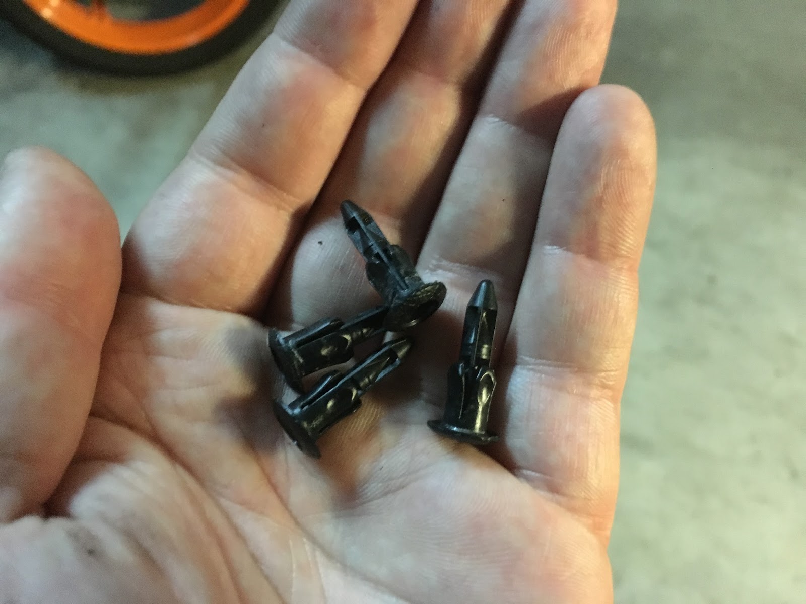

Step 4:
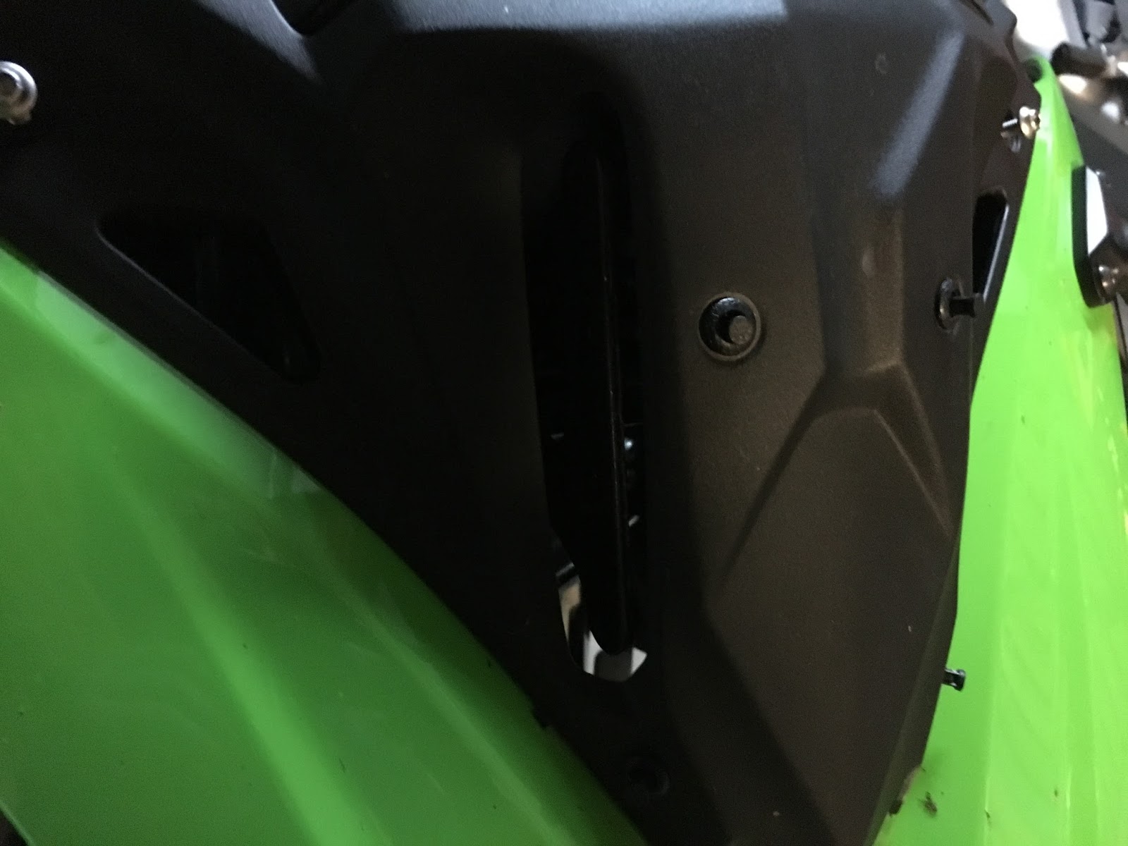
Now the front of your motorcycle should look like this:


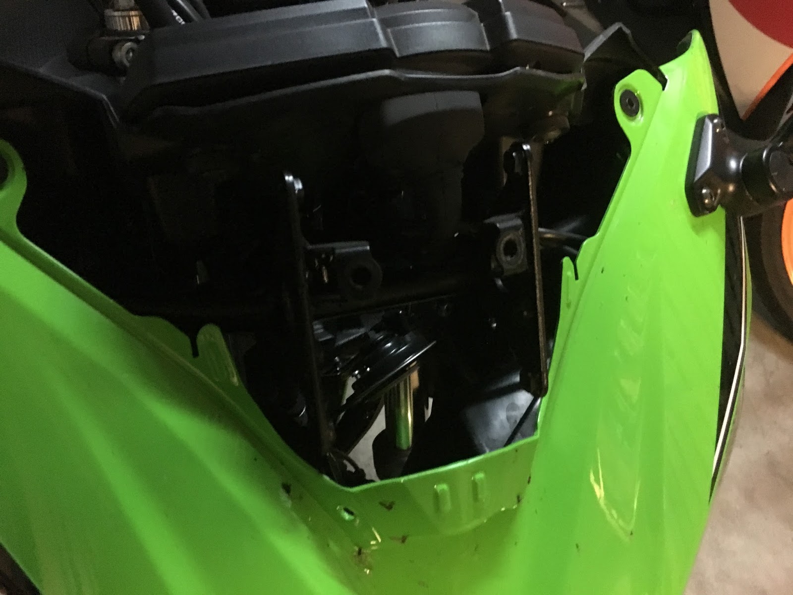
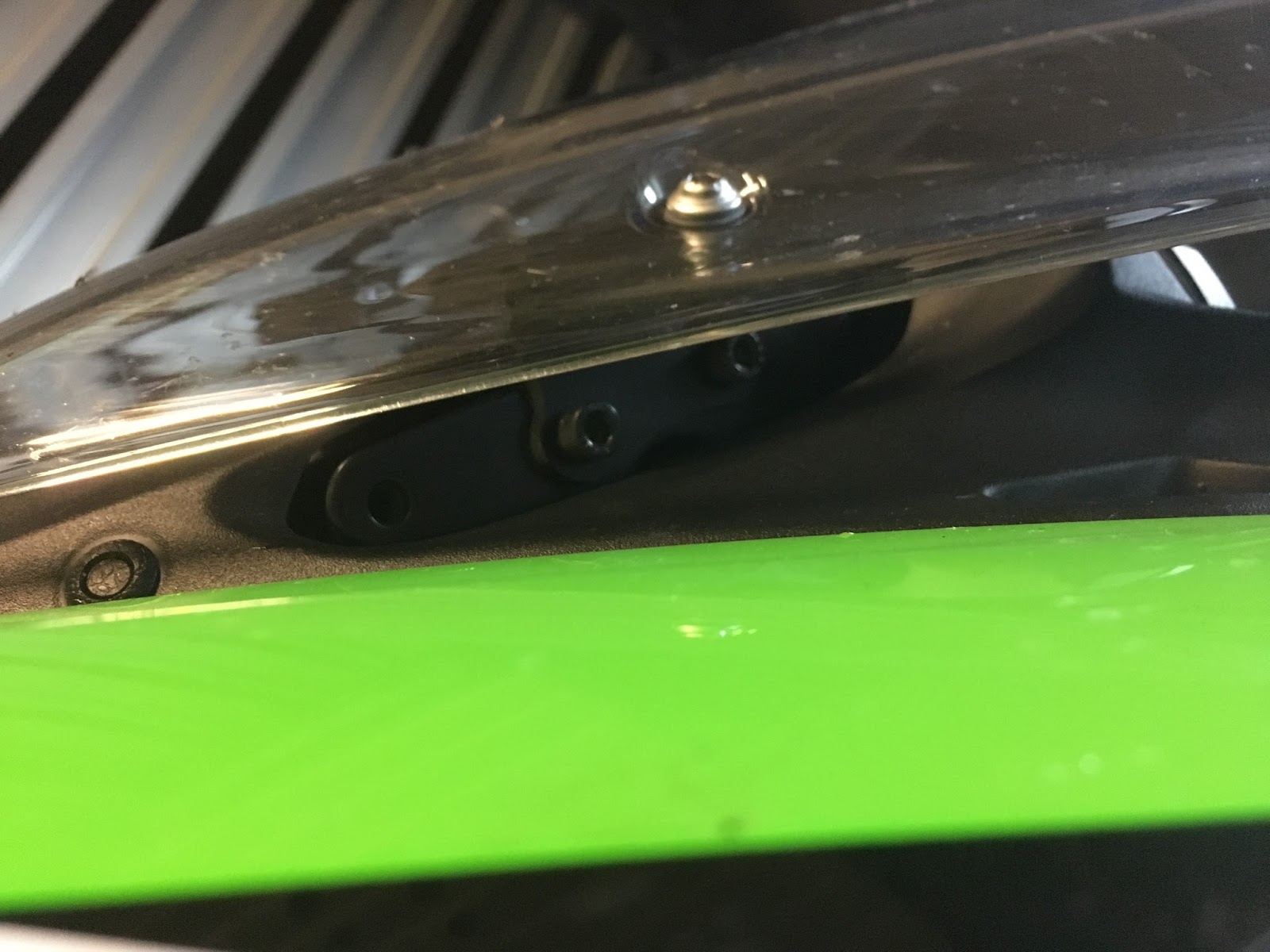
Look inside nearby socket hole and find two cables:
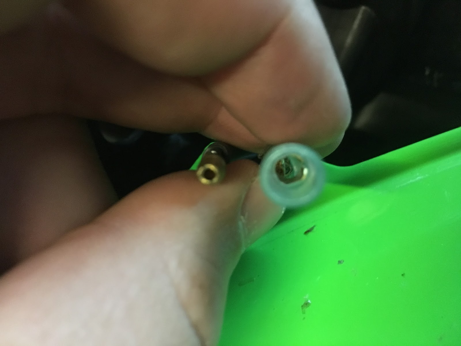

Step 5:
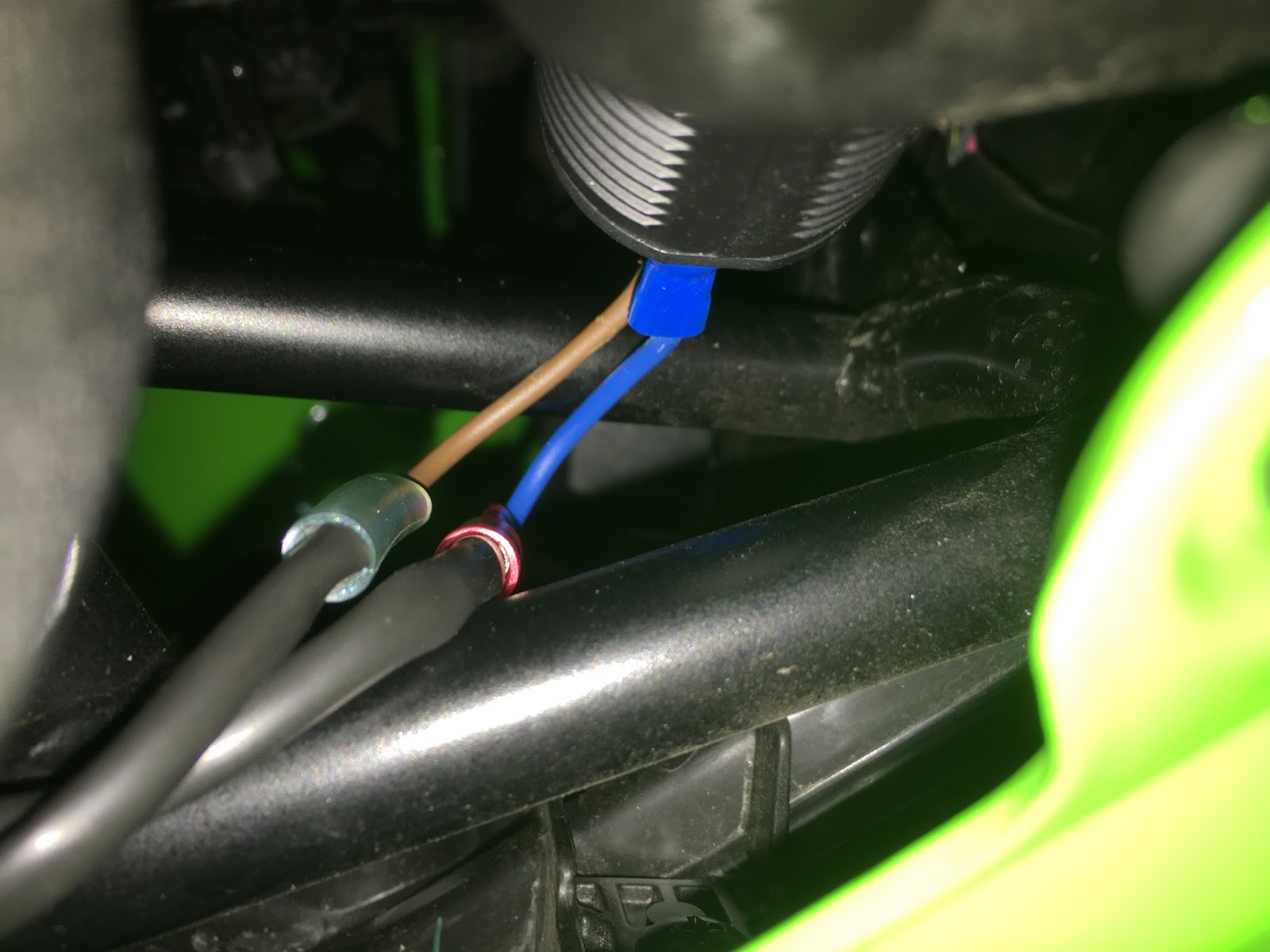
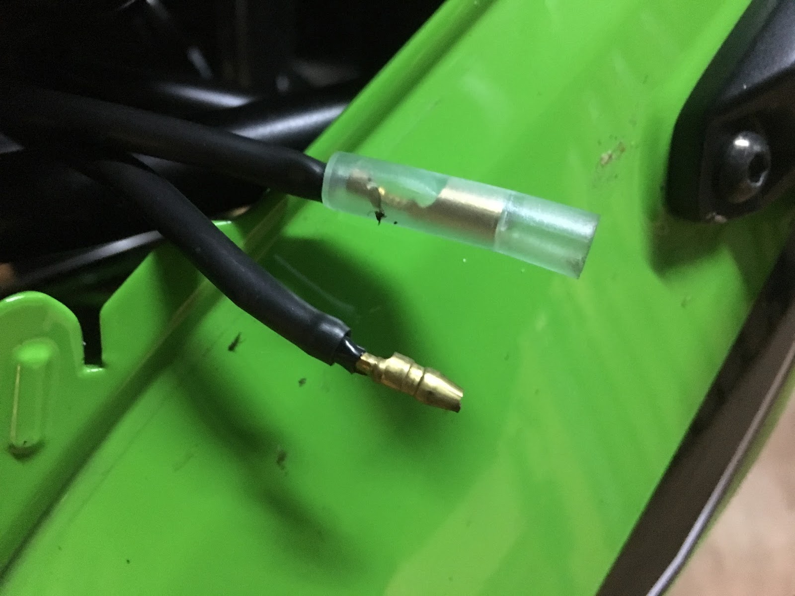
The most difficult part, prepare adapter cables. Required in my case because my usb socket has  flat connectors. There were 2 flat connectors already included with my Socket, I had to buy two round (4mm) connectors for less then $0.10 total - you can find them in nearby electric store. 5cm of cable which I already had, stripped from isolation on both ends, squeezed as hard as I could into connectors:


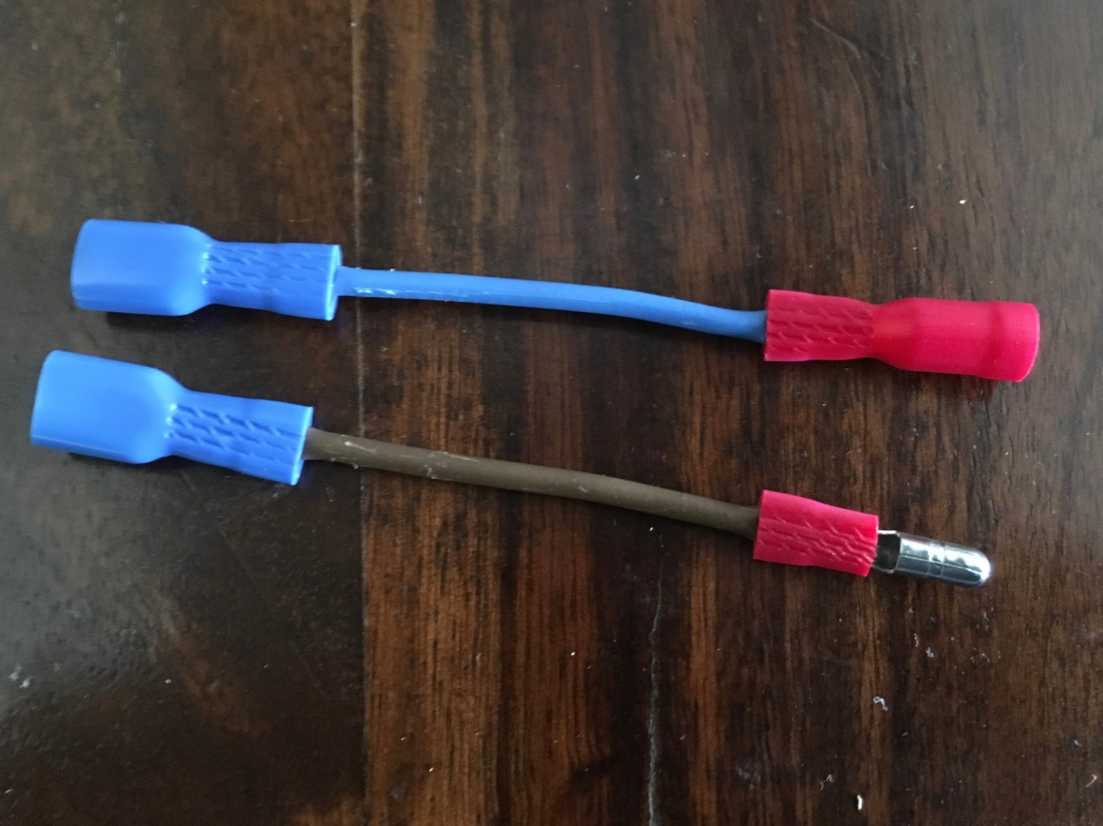
Almost ready to connect, one more thing - polarity is important, connecting improperly may cause damage. Verified with multimeter, female connector is positive (+) and male connector is ground (-)


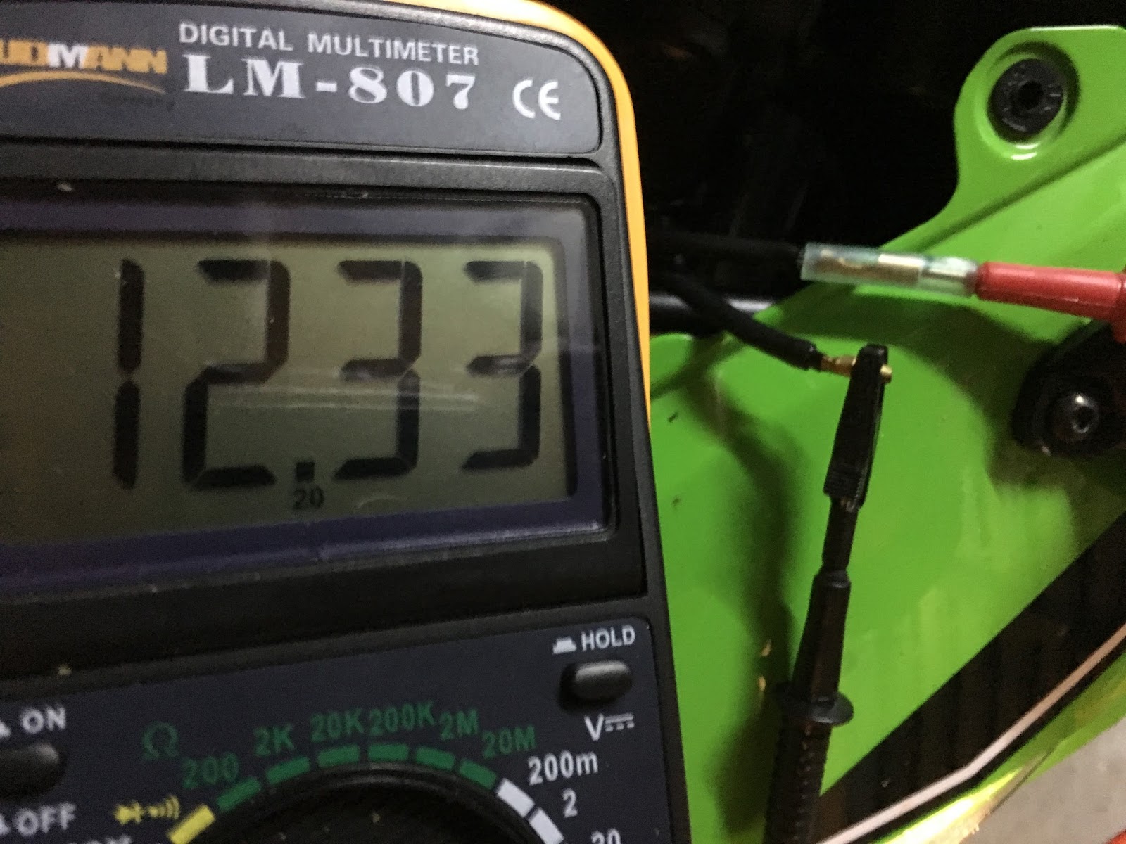
Motorcycle owner's manual says that this cables are already fused.

Step 6:
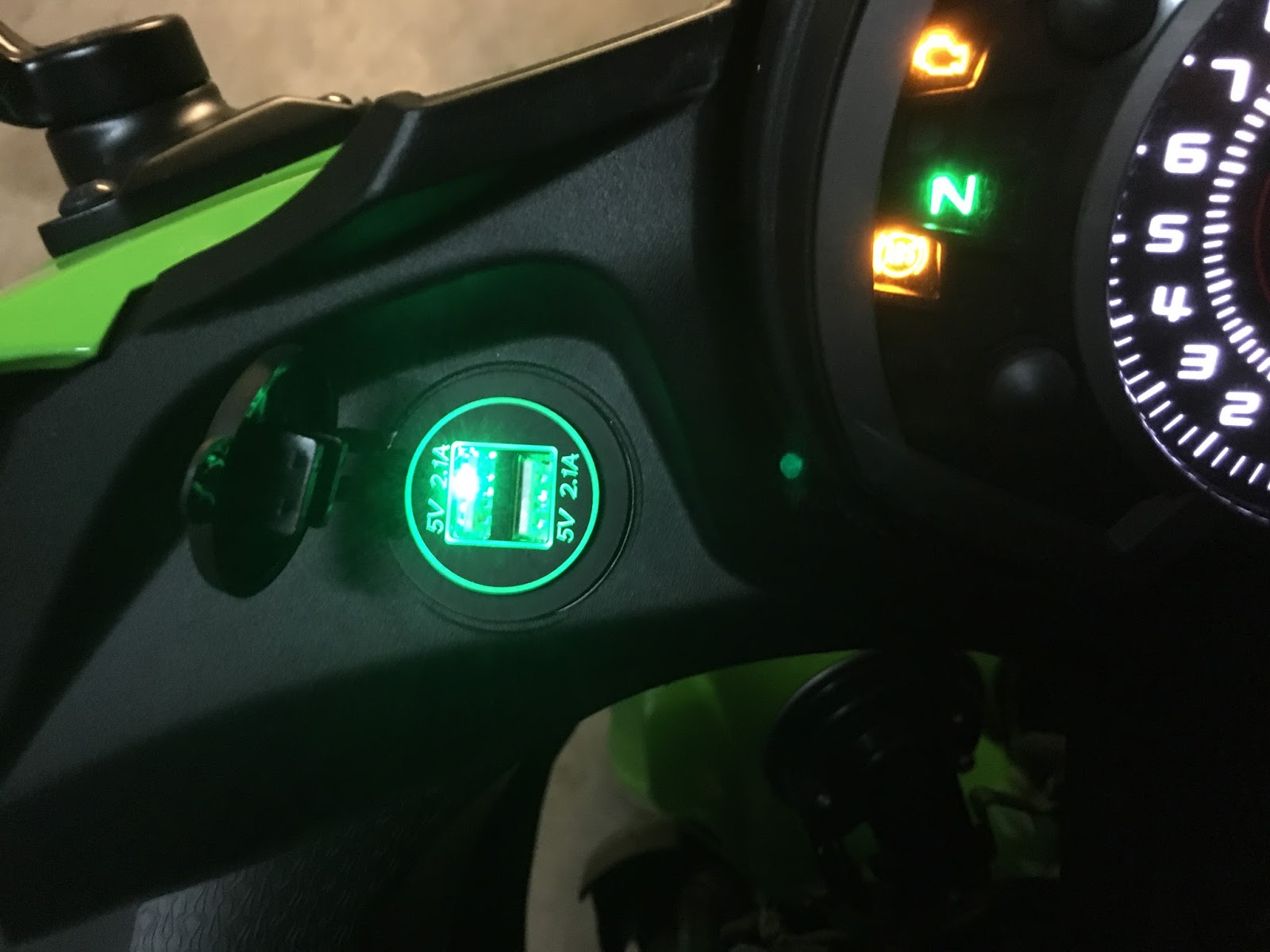
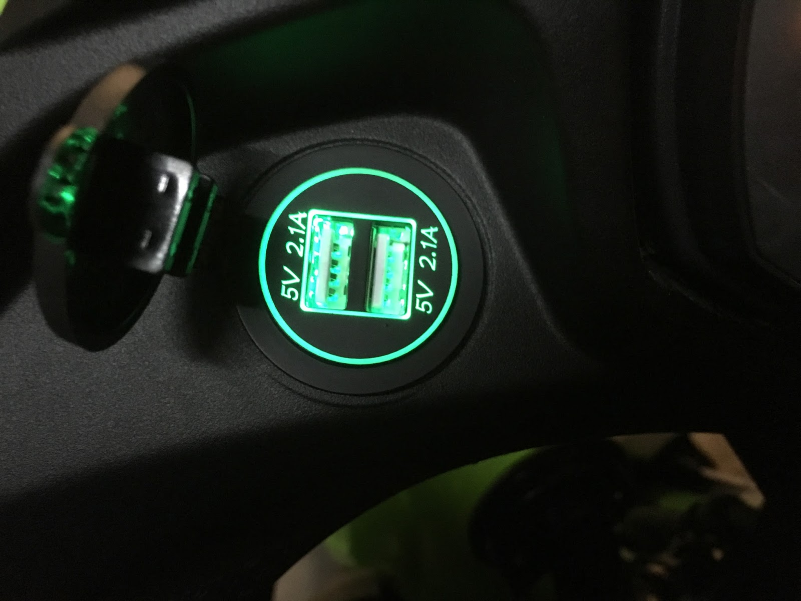
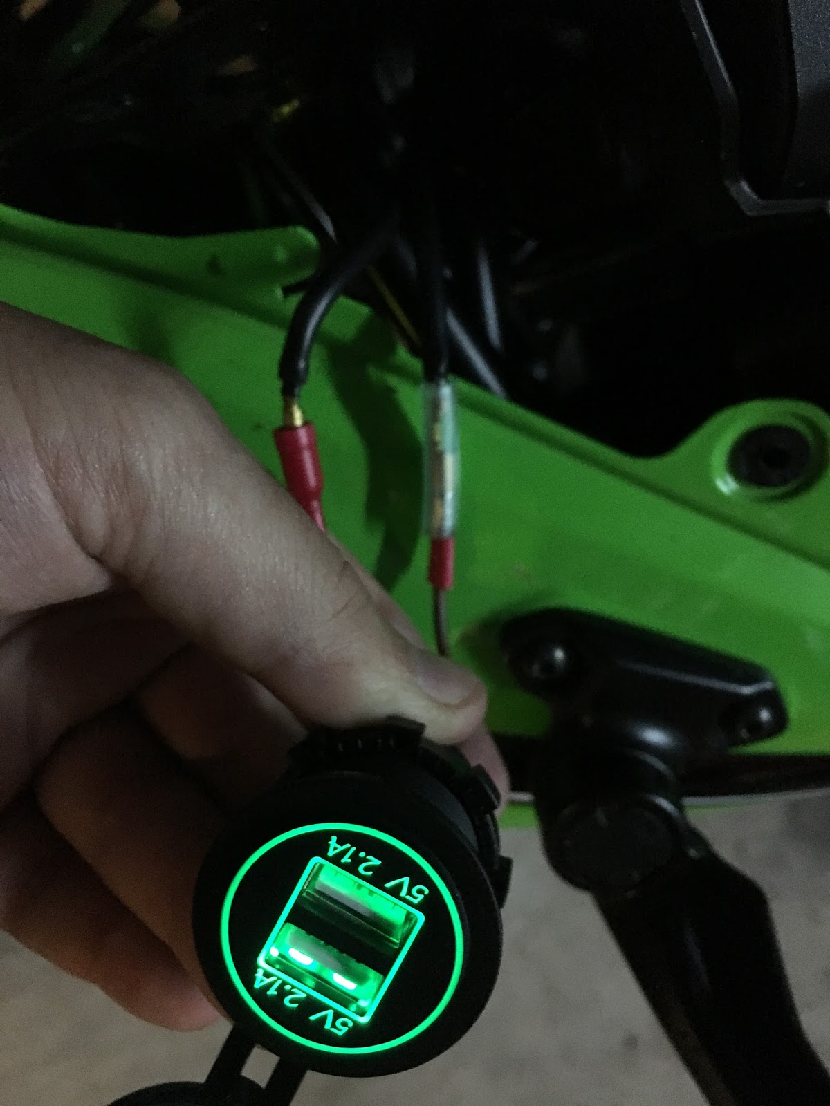
Connect all things together. Keep in mind polarity. Do not mount everything yet, it's always worth to check if it works before taking time to put things back together. Just connect the cables gently and turn the ignition key. My socket is illuminated so first impression was quite good. It's also good idea to verify it USB ports (both!) work correctly. I used my very old phone. Just in case. :)


After verification just disconnect the cables, put the socket into the hole (in my case it fits very very tightly so I had to turn it around several times). Secure with fastener ring. Replug the cables keeping in mind polarity, then retest.


If it works it's time to make sure that cables are connected firmly and put back the rest of the bike together. Enjoy your new $5 socket! :-)


Wednesday, October 11, 2017

Brother HL-2032 and osx - wireless printing (Linux)

Yep, still have this good old printer and it doesn't want to break. Quality is already bad but I'm not printing wedding invitations. Paper feed tends to get stuck every now and then. But I buy toner powder and refill it manually so it's extremely, extremely cheap. With that being said, I'm not really motivated to change. Anyways, when printing remotely from OSX or any other apple device, the best I was getting was just a ton of blank pages, the only way to stop this was actually to unplug power from the printer. So when I needed to print something I just had to walk to the printer, plug to USB and print directly. Not so bad, you have to get yourself to the printer to pick up your printouts anyway. Nothing else worked, including drivers from Brother or CUPS-supplied drivers. But recently I've finally managed to make it work - it was just a matter of spending some time trying different combinations of drivers and settings.

When I bought by raspberry I thought that maybe, just maybe I'll go ahead and try once again before I scrap it and buy something equipped with duplex, scanner, ADF and other fancy features. I've gone ahead and installed CUPS (apt install cups). Enabled remote configuration access - you need to edit /etc/cups/cupsd.conf and add there whatever is marked red:

# Only listen for connections from the local machine.
#Listen localhost:631
Port 631

# Restrict access to the server...
<Location />
  Order allow,deny
  Allow @local
</Location>

# Restrict access to the admin pages...
<Location /admin>
  Order allow,deny
  Allow @local
</Location>

# Restrict access to configuration files...
<Location /admin/conf>
  AuthType Default
  Require user @SYSTEM
  Order allow,deny
  Allow @local
</Location>


Reload CUPS (/etc/init.d/cups restart) and you should be able to go to http://your-cups-box:631/ and see CUPS configuration page.


Okay, looks like the hardest part is done. Now click on "Add Printer", then select your Brother HL-2032 printer and click "Continue".


Select whatever name/description/location you feel comfortable for your printer (and of course Share) and move forward...


And now the tricky part - drivers:


Go to http://www.openprinting.org/printer/Brother/Brother-HL-2030 and download HL-2030 drivers PPD file (use "Directly download PPD" link)


Now get back to CUPS page and select "Or provide a PPD file:" and choose downloaded file (Brother-HL-2030-hl1250.ppd). Next page will ask you a couple of questions about settings:

Now you are good to go. Try to print a test page, should work like a charm.


Sunday, February 5, 2017

NodeMCU and OSX

During my adventure with NodeMCU, ESP9266 and DHT22 I had to switch from Windows machine to Macbook. Looks like having it running from OSX is as easy as at windows.

Step 1: Download and install CP210x USB to UART Bridge VCP Drivers
Step 2: Connect your NodeMCU and verify if you have USB serial port available


Step 3: Connect to this virtual COM using your favorite terminal emu. Remember to adjust settings (Default: 9600/8/N/1). Screen is the one you probably already have. If you didn't change default configuration then you are ready to go. Just type `screen /dev/tty.SLAB_USBtoUART`


Works like a charm.

Flashing firmware is also easy. You have to have python and pip installed. Python is already there. All you have to do is `sudo easy_install pip`. 
After pip is installed you can use it to install esp tool by using command `pip install esptool`:


Now we can try to install some software. Little bit more complicated, but can survive. In order to enable flashing of device, GPIO0 must be set to low. It can be done by pressing "FLASH" button during powering on (just keep it pressed as you plug it into USB port). Also remember to disconnect your terminal from serial port. I was able to reflash my NodeMCU using this method easily.


After that just replug your device, open back terminal emulator and reconnect to serial interface. You are back in the business. What is also quite interesting, after flashing on Windows I had to upload init.lua again, this time it was not removed.

So yea, one last thing to learn would be how to up(down)load files. Need another cool tool to be installed - nodemcu-uploader. Procedure exactly the same as before. Note, disconnect your terminal and according to instructions, as we use old firmware, change baudrate to 9600.


Now we can fully work with NodeMCU from OSX directly.
You can continue with this guide. Only difference is - you will have to enter all commands manually.


Getting more of LUA and NodeMCU

In my first and second article about making home smart, we managed to build the sensor, connect it, install firmware and do some basic things like lighting LED or reading temperature and humidity data from sensor. Now it's time to do some serious coding. This is the place where I spent most of my time with NodeMCU so far. Not because it's so complex - LUA is quite friendly and simple. If you did some coding with Perl or Python, this would be very easy for you.


Let's start properly - there's LUA book available on-line, called Programming in Lua. First edition is available on-line and even though you are probably already familiar with scripting, it's good to review it on a fast forward just to know what's going on.

Second very importand resource is this page. It tells you everything that you have to know in order to be succesfull with various devices you might want to connect to your unit.

Okay, let's get started. We already have some experience and we know how to light up the diode and how to read the sensor data. Now it's time to write down code, which will run during module bootup, start WiFi, connect to the network and read our sensor periodically. Let's keep things simple for the time being and just display the data. Sending it somewhere will be our next step.

As you might have noticed, after MCU starts, it displays message "cannot open init.lua".


This is the file that firmware use to start whatever script we want to execute. 
Let's try with some basic code (most of it we already got from Lua Loader by just clicking! :))

print("Connecting to wifi SSID wifi-name")
wifi.setmode(wifi.STATION)
wifi.sta.config("wifi-name","wifi-password")

status=wifi.sta.status()
if status == 5 then
print(string.format("Wifi Connected succesfully (%d)",status))
sid,pwd,bssid = wifi.sta.getconfig()
print("Wifi SSID: ", ssid)
print("Wifi IP: ",wifi.sta.getip())
print("Assuming normal operations.")
else
print(string.format("Wifi Not Connected (%d).",status))
end

pin=2
gpio.mode(4,gpio.OUTPUT)
gpio.write(4,0)
status, temp, humi, temp_dec, humi_dec = dht.read(pin)
gpio.write(4,1)

if status == dht.OK then
print(string.format("DHT Temperature: %.1f;Humidity: %.1f%%\r\n",temp,humi ))
else
print("Fatal: Invalid Read from DHT")
end

Okay, cool. We have something that works. By the way, I light up blue LED while data is read from the sensor. This act as a gadget as well as visual keep-alive. In the future when it will be installed it will be very easy to verify if it works by looking at it.

Normally our approach would be to have it in the loop with some delay in order to have it done periodically. At least sensor part. What if connection to wifi takes longer than execution of code? We also have to include some delay here and retry in case of failure.

With my little experience with this platform, seems that introducing delay may be quite difficult and this is supposed to be event driven. So I found two useful ways to do this

Just like with LuaLoader, I went for timers just because I found them first.

So here's the idea:
- turn WiFi verification and sensor read into functions
- start WiFi Association
- start reoccuring timer for 1 second, every time it fires verification of WiFi happens
- if negative, do nothing, just keep it running every second
- if positive, remove timer and start another timer which will trigger sensor function periodically.

-- 1. Initiate connection to WiFi:
print("Connecting to wifi SSID wifi-name")
wifi.setmode(wifi.STATION)
wifi.sta.config("wifi-name","wifi-password")

-- 2. Turn wifi verification to a function
function checkwifi()
  status=wifi.sta.status()
  if status == 5 then
    print(string.format("Wifi Connected succesfully (%d)",status))
    ssid,pwd,bssid = wifi.sta.getconfig()
    print("Wifi SSID: ", ssid)
    print("Wifi IP: ",wifi.sta.getip())
    print("Assuming normal operations.")
-- 6. If we detect that Wifi Connection is successful
-- terminlate timer ID 0 and start new timer ID 1
-- which will run every 15 seconds and trigger getdht()
    tmr.unregister(0)
    tmr.alarm(1,15000,1,function() getdht() end)
  else
    print(string.format("Wifi Not Connected (%d). Retrying in 1 second...",status))
  end
end

-- 3. Turn sensor read into function
function getdht()
  pin=2
  gpio.mode(4,gpio.OUTPUT)
  gpio.write(4,0)
  status, temp, humi, temp_dec, humi_dec = dht.read(pin)
  gpio.write(4,1)

  if status == dht.OK then
    print(string.format("DHT Temperature: %.1f;Humidity: %.1f%%\r\n",temp,humi ))
  else
    print("Fatal: Invalid Read from DHT")
  end
end

-- 4. After everything is set up print a message:
print("Waiting 1 second for WiFi init...")
-- 5. Start 1-second (1000) reoccuring (tmr.ALARM_AUTO) timer
-- with ID 0 (0).
-- Once triggered it will run checkwifi() and start over.
tmr.alarm(0,1000,tmr.ALARM_AUTO,function() checkwifi() end)

Now you can copy-paste this to your notepad, remove comments, adjust to whatever wifi name or timer values you need and copy it to your clipboard. Go to your Lua Loader and click "Paste Text" button. It will paste your clipboard directly to the console. You probably want to hit "Restart" button before you do that and remove whitespaces from the beginning of the lines as Lua Loader doesn't like them.


Let's make sure this code will be executed automatically every time our device boots. Save it as init.lua and copy to the device using Lua Loader.

Okay, script loaded, let's reset once again and see results.
In the next part we will see how to send this data to another device through WiFi and use them.


First steps with ESP8266, DHT22 and LUA

If you get here, hopefully you already have your  board connected. If not, please refer to my previous article as it explains this proces step by step.
First interesting feature of Lua Loader is ability to generate some Lua code for us by just hitting buttons. It is also useful to learn as code generated based on our input is displayed on the main window.
Enter your SSID and password and click "Set AP". In main window you should see commands required to establish WiFi connectivity:

You can try to hit "Get IP" "Survey" and this green icon in the middle - it provides WiFi status. You can also terminate this connection if you wish by hitting Disconnect buton.

Great stuff, lets try something else. There is LED diode localized near to WiFi Antenna. It is connected to GPIO pin 04 and we can light it. On the right hand side you can see blue "GPIO" panel.
Set it to the following values and click "Set" then click "0".
Led should be now shining blue. Additionally, two lines of Lua code required to achieve this result are generated and displayed in the main window:
If you want to turn it off, click on "1".

Okay, great, so far so good. We finally get to the point where have board running, tested with some basic features. It's time to understand pinouts and connect DHT sensor. (Please google for nodemcu pinout)

And let's take a closer look on our sensor. It comes with two version - sensor only which has four pins and sensor mounted on PCB which I have. For the first one you gonna need additional resistor in order to connect things properly. With my version it's all about connecting right pins together. They are described as "GND", "ACC" and "DAT". GND is quite descriptive,  must be connected to "GND" on ESP board. ACC is +3,3V and we connect it to "3V3" pin. last one is Data and this should be connected to any of GPIO pinouts.

On ESP itself you will see multiple pins with GND or 3V3 descriptions. It doesn't matter which one you use, they are multiplied for covenience. This is how I connected things:


I used pin described as D2 (PIN2) which is in fact GPIO04 pin.

Let's make this thing finally useful and see current temperature and humidity then.

Great! We are now able to read temperature and humidity values from the sensor. In the next section we will try to make it automatic and somehow transmitted to HomeKit software.


Smart Home: HomeKit, MQTT, DHT22, ESP8266, LUA and NodeMCU.

Inspired by my friend and humidity issues in my bathroom I decided to have some fun and start making my home more inteligent.

First attempt - make humidity and temperature sensor which will present data on my iPhone "Home" App. While it looks not complicated when we split it into pieces we need the following components:


- Temperature/Humidity Sensor //DHT22
- Wireless module, capable of reading sensor data and sending it somewhere // ESP8266/NodeMCU
- Some software smart enough to receive and understand data from sensor, identify from which potential sensor this data comes and forward it into HomeKit // MQTT
- Homekit software to talk with phone
- Phone who will read and present data from HomeKit software

I ordered by ESP and DHT on most popular chinesee portal and I aimed for cheapest, so both cost me together a couple of bucks. DHT was delivered quite on time and in good shape, however ESP was more then 3 months in transit and looks like crap. Surprisingly, it works just fine :-)


In order to get started with ESP we need couple of things:
- USB cable
- ESP Flasher
- ESP firmware
- IDE

Start here if you use OSX or Linux machine.

Once you connect your ESP to windows machine with USB you should already see first signs of life from your module, blue led near WiFi antenna should blink randomly. Go to Settings -> Devices -> Connected Devices and look for something like this:

If you see it - great, your USB to Serial driver works just fine and your virtual COM port is whatever the numer is (my case - COM3)

Next step - flash your ESP with new software. Optional, but you will definitely have to flash your ESP multiple times and it's a piece of cake so let's make sure we have newest firmware on it. (And, by the way, if you are already here, it's just about time to at least  browse this resource - you will need it all the time while playing around with your ESP).

You can try to build  your own firmware here but I didn't bother. For the 1st time I just used last pre-compiled image available here. There are two flavors of image, float and integer. I took float, why not?

Yea, it was build almost year ago, but again, for the starter, we don't need fireworks.
Flasher sits here along with short instruction how to use it. Just download 32bit or 64bit exec file and run. Go to config tab and click on gearwheel icon, select your firmware, leave offset at 0x0. Then get back to operation, make sure your COM port is set properly and click FLASH button. Progress bar should start becoming green and your firmware should be present on ESP in a couple of minutes.
Now it's time to see what this little baby can do for us. By the way, if flashing does not work for some reason, just disconnect everything you might have already connected to the unit.

There is a couple of different IDEs to use with this board, I picked up LuaLoader for no good reason While bit annoying if you want to talk to your device interactively, it works fine.

All you need to do is to download executable and run it. Go to Settings -> Comm Port Settings.
Then configure your serial port as presented.
Then, hit Connect (Right to Settings). Then red "Restart" buton on right hand side. You should see something like this in main window.

If you see this - Excellent. Now it's time to do something useful with your dev board.