In my
first and
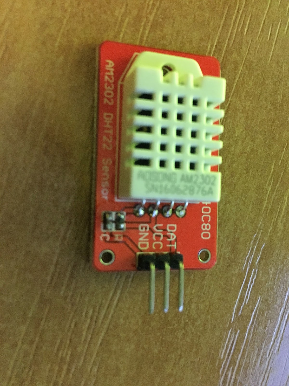
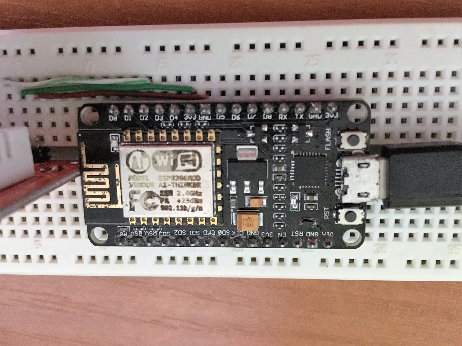
second article about making home smart, we managed to build the sensor, connect it, install firmware and do some basic things like lighting LED or reading temperature and humidity data from sensor. Now it's time to do some serious coding. This is the place where I spent most of my time with NodeMCU so far. Not because it's so complex - LUA is quite friendly and simple. If you did some coding with Perl or Python, this would be very easy for you.
Let's start properly - there's LUA book available on-line, called
Programming in Lua. First edition is available on-line and even though you are probably already familiar with scripting, it's good to review it on a fast forward just to know what's going on.
Second very importand resource is
this page. It tells you everything that you have to know in order to be succesfull with various devices you might want to connect to your unit.
Okay, let's get started. We already have some experience and we know how to light up the diode and how to read the sensor data. Now it's time to write down code, which will run during module bootup, start WiFi, connect to the network and read our sensor periodically. Let's keep things simple for the time being and just display the data. Sending it somewhere will be our next step.
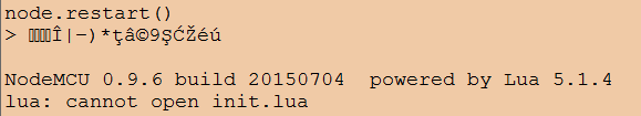
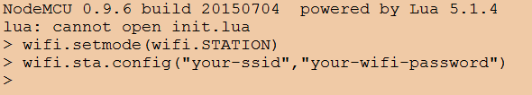
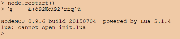
As you might have noticed, after MCU starts, it displays message "cannot open init.lua".
This is the file that firmware use to start whatever script we want to execute.
Let's try with some basic code (most of it we already got from Lua Loader by just clicking! :))
print("Connecting to wifi SSID wifi-name")
wifi.setmode(wifi.STATION)
wifi.sta.config("wifi-name","wifi-password")
status=wifi.sta.status()
if status == 5 then
print(string.format("Wifi Connected succesfully (%d)",status))
sid,pwd,bssid = wifi.sta.getconfig()
print("Wifi SSID: ", ssid)
print("Wifi IP: ",wifi.sta.getip())
print("Assuming normal operations.")
else
print(string.format("Wifi Not Connected (%d).",status))
end
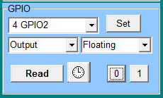
pin=2
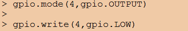
gpio.mode(4,gpio.OUTPUT)
gpio.write(4,0)
status, temp, humi, temp_dec, humi_dec = dht.read(pin)
gpio.write(4,1)
if status == dht.OK then
print(string.format("DHT Temperature: %.1f;Humidity: %.1f%%\r\n",temp,humi ))
else
print("Fatal: Invalid Read from DHT")
end
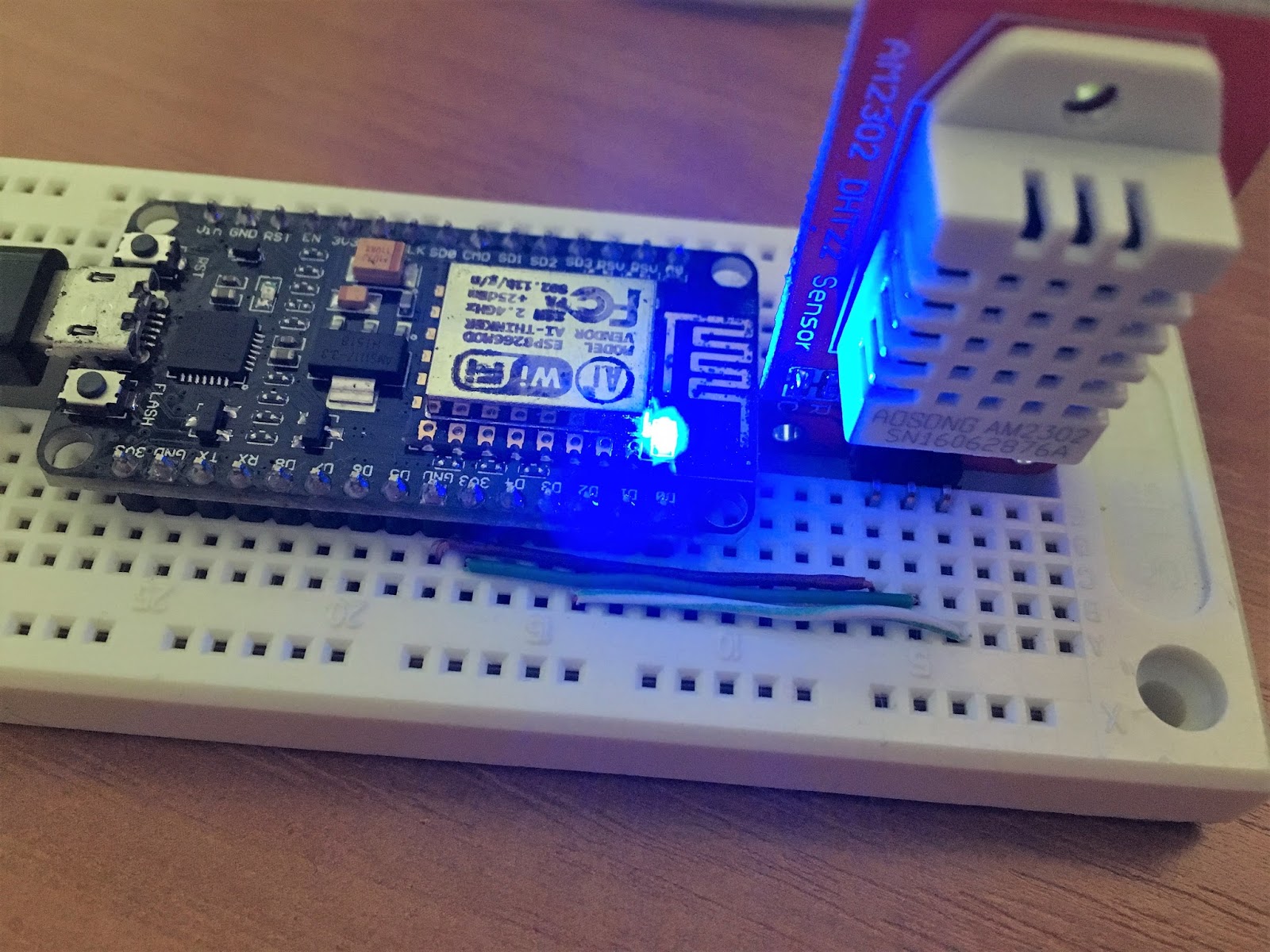
Okay, cool. We have something that works. By the way, I light up blue LED while data is read from the sensor. This act as a gadget as well as visual keep-alive. In the future when it will be installed it will be very easy to verify if it works by looking at it.
Normally our approach would be to have it in the loop with some delay in order to have it done periodically. At least sensor part. What if connection to wifi takes longer than execution of code? We also have to include some delay here and retry in case of failure.
With my little experience with this platform, seems that introducing delay may be quite difficult and this is supposed to be event driven. So I found two useful ways to do this
Just like with LuaLoader, I went for timers just because I found them first.
So here's the idea:
- turn WiFi verification and sensor read into functions
- start WiFi Association
- start reoccuring timer for 1 second, every time it fires verification of WiFi happens
- if negative, do nothing, just keep it running every second
- if positive, remove timer and start another timer which will trigger sensor function periodically.
-- 1. Initiate connection to WiFi:
print("Connecting to wifi SSID wifi-name")
wifi.setmode(wifi.STATION)
wifi.sta.config("wifi-name","wifi-password")
-- 2. Turn wifi verification to a function
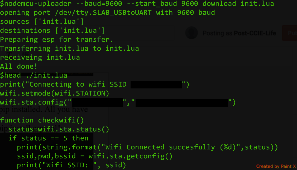
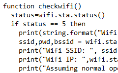
function checkwifi()
status=wifi.sta.status()
if status == 5 then
print(string.format("Wifi Connected succesfully (%d)",status))
ssid,pwd,bssid = wifi.sta.getconfig()
print("Wifi SSID: ", ssid)
print("Wifi IP: ",wifi.sta.getip())
print("Assuming normal operations.")
-- 6. If we detect that Wifi Connection is successful
-- terminlate timer ID 0 and start new timer ID 1
-- which will run every 15 seconds and trigger getdht()
tmr.unregister(0)
tmr.alarm(1,15000,1,function() getdht() end)
else
print(string.format("Wifi Not Connected (%d). Retrying in 1 second...",status))
end
end
-- 3. Turn sensor read into function
function getdht()
pin=2
gpio.mode(4,gpio.OUTPUT)
gpio.write(4,0)
status, temp, humi, temp_dec, humi_dec = dht.read(pin)
gpio.write(4,1)
if status == dht.OK then
print(string.format("DHT Temperature: %.1f;Humidity: %.1f%%\r\n",temp,humi ))
else
print("Fatal: Invalid Read from DHT")
end
end
-- 4. After everything is set up print a message:
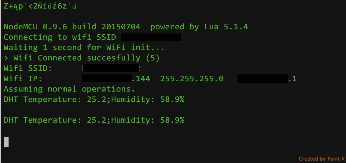
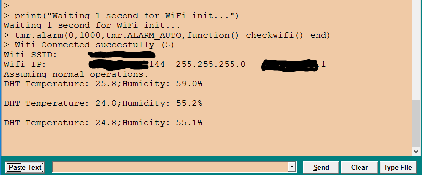
print("Waiting 1 second for WiFi init...")
-- 5. Start 1-second (1000) reoccuring (tmr.ALARM_AUTO) timer
-- with ID 0 (0).
-- Once triggered it will run checkwifi() and start over.
tmr.alarm(0,1000,tmr.ALARM_AUTO,function() checkwifi() end)
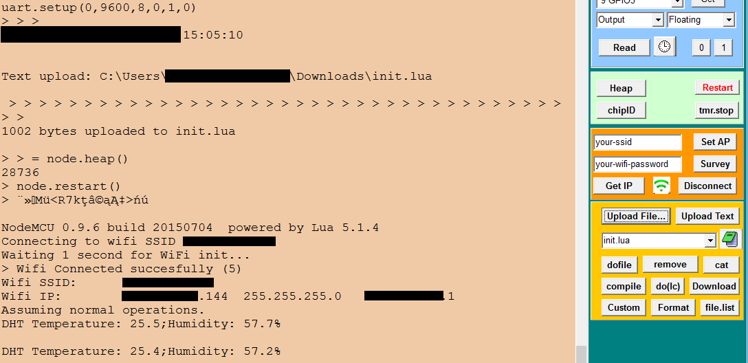
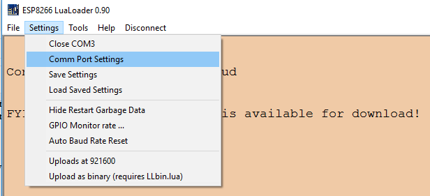
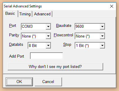
Now you can copy-paste this to your notepad, remove comments, adjust to whatever wifi name or timer values you need and copy it to your clipboard. Go to your Lua Loader and click "Paste Text" button. It will paste your clipboard directly to the console. You probably want to hit "Restart" button before you do that and remove whitespaces from the beginning of the lines as Lua Loader doesn't like them.
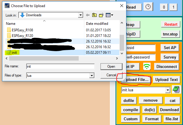
Let's make sure this code will be executed automatically every time our device boots. Save it as init.lua and copy to the device using Lua Loader.
Okay, script loaded, let's reset once again and see results.
In the next part we will see how to send this data to another device through WiFi and use them.