 If you get here, hopefully you already have your board connected. If not, please refer to my previous article as it explains this proces step by step.
First interesting feature of Lua Loader is ability to generate some Lua code for us by just hitting buttons. It is also useful to learn as code generated based on our input is displayed on the main window.
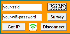
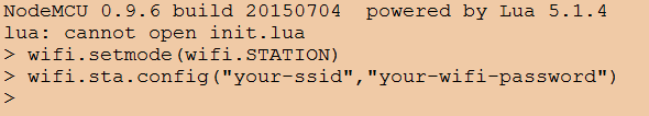
Enter your SSID and password and click "Set AP". In main window you should see commands required to establish WiFi connectivity:
You can try to hit "Get IP" "Survey" and this green icon in the middle - it provides WiFi status. You can also terminate this connection if you wish by hitting Disconnect buton.
Great stuff, lets try something else. There is LED diode localized near to WiFi Antenna. It is connected to GPIO pin 04 and we can light it. On the right hand side you can see blue "GPIO" panel.
Set it to the following values and click "Set" then click "0".
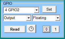
Led should be now shining blue. Additionally, two lines of Lua code required to achieve this result are generated and displayed in the main window:
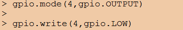
If you want to turn it off, click on "1".
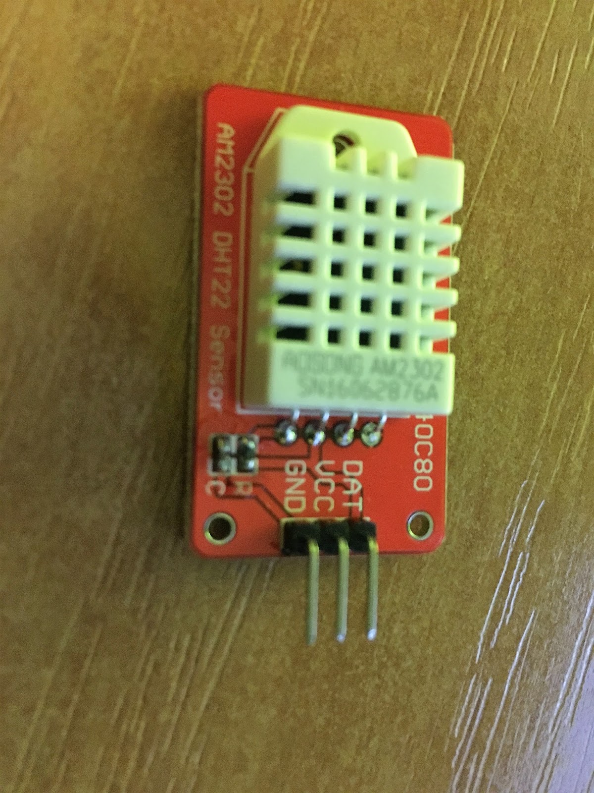
Okay, great, so far so good. We finally get to the point where have board running, tested with some basic features. It's time to understand pinouts and connect DHT sensor. (Please google for nodemcu pinout)
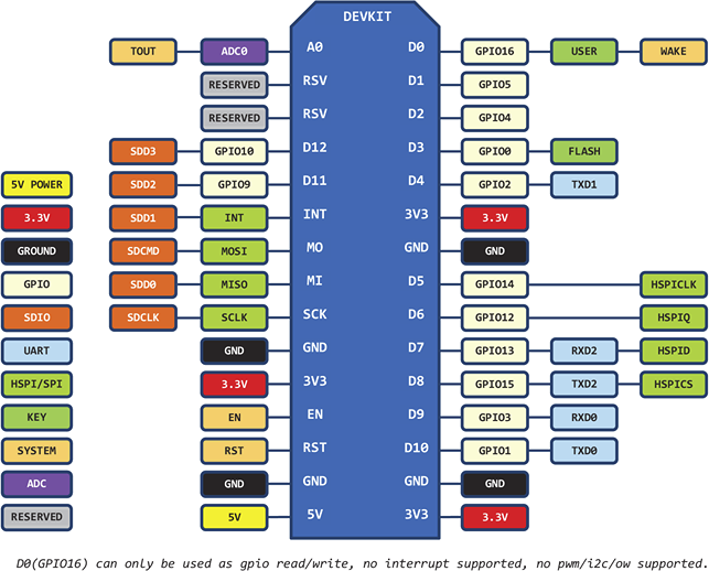
And let's take a closer look on our sensor. It comes with two version - sensor only which has four pins and sensor mounted on PCB which I have. For the first one you gonna need additional resistor in order to connect things properly. With my version it's all about connecting right pins together. They are described as "GND", "ACC" and "DAT". GND is quite descriptive, must be connected to "GND" on ESP board. ACC is +3,3V and we connect it to "3V3" pin. last one is Data and this should be connected to any of GPIO pinouts.
On ESP itself you will see multiple pins with GND or 3V3 descriptions. It doesn't matter which one you use, they are multiplied for covenience. This is how I connected things:

I used pin described as D2 (PIN2) which is in fact GPIO04 pin.
Let's make this thing finally useful and see current temperature and humidity then.
No comments:
Post a Comment